adding a neopixel ring to the black adafruit feather rp2040

Two posts back I wrote about adding a NeoPixel stick with eight NeoPixels to the Black Adafruit Feather RP2040. In this quick post I take the code from the Feather STM32 driving the NeoPixel stick and quickly “port” it to the Feather RP2040 driving a NeoPixel ring with 12 NeoPixel LEDs. Both Feathers are running their specific version of Circuit Python version 7.1.1. The story behind how I acquired the NeoPixel ring is interesting. One day last year, while visiting the Parallax website ( https://www.parallax.com ) I came across a sale of a mystery box of components (Adafruit has the equivalent). So I bit and bought one, just to see what I’d get. When the mystery box arrived it had a lot of interesting components, one of which was the NeoPixel ring. I had no use for the ring at the time and put it back in the box and put the box on the shelf with a lot of other boxes with components I keep in case… Forward six months or so and I came across a sale of the NeoPixel sticks, so I bought one along with the STM32 Feather.

Today as I was cleaning and reorganizing I came across that mystery box and remembered I had the NeoPixel ring in it. I pulled it out, soldered some wires to it, plugged it into the Feather RP2040 using the same pins as with the Feather STM32 and copied the STM32’s code over to the RP2040. I had to make two changes to one line of code at line 14:

  1. Change the number of NeoPixel LEDS from 8 to 12, and
  2. Change the NeoPixel type from neopixel.GRBW to neopixel.GRB because there is no white on the NeoPixel ring.

Once that was done the behavior of the NeoPixel ring was essentially identical with the NeoPixel stick.

import timeimport boardimport neopixel # For the single neopixel on the feather itself.#sneopixel = neopixel.NeoPixel(board.NEOPIXEL, 1, brightness=0.2, auto_write=False, pixel_order=neopixel.GRB) # For the eight neopixel board attached to the feather.#pixelboard = neopixel.NeoPixel(board.D5, 12, brightness=0.2, auto_write=True, pixel_order=neopixel.GRB) def cycleColor(color):sneopixel.fill(color)sneopixel.show()for i in range(len(pixelboard)):pixelboard[i-1] = (0,0,0,0) # turn LED offpixelboard[i] = colorpixelboard.show()time.sleep(.05) while True:cycleColor((64,0,0,0)) # redcycleColor((0,64,0,0)) # greencycleColor((0,0,64,0)) # bluecycleColor((64,16,0,0)) # orangecycleColor((0,32,32,0)) # cyancycleColor((0,0,0,0)) # black (LED off)

And once again the video clip was made with my iPhone 11 Pro, and it’s as crappy as the last one. I will work diligently to learn how to do a much better job of videoing these types of devices. They look far better in person.

tinkering with the black adafruit feather rp2040

Everyone by now should know reflexively what the Raspberry Pi RP2040 is ( see https://www.raspberrypi.com/products/raspberry-pi-pico/ if you don’t). It comes in a number of variants from the bare chip to the Pico from Raspberry Pi (with and without headers) to board offerings from Adafruit, Sparkfun, and other board makers. So far I’ve purchased several Picos and several Black Adafruit Feather RP2040s. I’ve powered up both and worked with both, programming them in MicroPython (Pico), C++ (Pico), and CircuitPython (Adafruit). In this post I’m writing about the Adafruit version ( https://www.adafruit.com/product/4884 ). I’ve also purchased and installed one Featherwing OLED — 128×32 Add-on ( https://www.adafruit.com/product/2900 ). I’m interested in that add-on because of its display as well as the three buttons also mounted on the Featherwing. This post is about just the display.

The majority of this code was copied from an example on the Adafruit website ( https://learn.adafruit.com/adafruit-oled-featherwing/python-usage ), starting with the instructions on how to set up the RP2040’s CircuitPython runtime environment.  I copied the example code a few lines at a time to see what happened as each block was pasted in. It was interesting how everything behaved as each block was pasted in and the entire body restarted.

My version of the code has a problem, and it all started with an innocent desire to change the text inside the Label text_area (see line 45). Every other user interface framework that defines label classes provides a simple class method to change the label’s text. I looked but couldn’t find a good public method. Instead I used what is, but Python convention, a somewhat private internal method _update_text() (lines 63 and 65). This coding convention is spelled out in PEP 8:

A name prefixed with an underscore (e.g. _spam) should be treated as a non-public part of the API (whether it is a function, a method or a data member). It should be considered an implementation detail and subject to change without notice.

My use is thus a poor example. But I’ve yet to find the “proper” example. If and when I ever do, then I’ll update the code. But for the mean time I’ll live with it.

I need that capability for my next stage, which is to show via the OLED display when I press button ‘A’, ‘B’, or ‘C’.

import boardimport displayioimport terminaliofrom adafruit_display_text import labelimport adafruit_displayio_ssd1306import time# Initialize the I2C bus connected to the display.# Initialize the display.#displayio.release_displays()i2c = board.I2C()display_bus = displayio.I2CDisplay(i2c, device_address=0x3C)display = adafruit_displayio_ssd1306.SSD1306(display_bus, width=128, height=32)# Fill the background with white. # This is a monochrome display, so there can be only black # or white.#splash = displayio.Group()display.show(splash)color_bitmap = displayio.Bitmap(128, 32, 1)color_palette = displayio.Palette(1)color_palette[0] = 0xFFFFFF  # Whitebackground_sprite = displayio.TileGrid(color_bitmap, pixel_shader=color_palette, x=0, y=0)splash.append(background_sprite)# Draw a black inner rectangle.#inner_bitmap = displayio.Bitmap(122, 28, 1)inner_palette = displayio.Palette(1)inner_palette[0] = 0x000000  # Blackinner_sprite = displayio.TileGrid(inner_bitmap, pixel_shader=inner_palette, x=3, y=2)splash.append(inner_sprite)# Create a text label in the center of the inner rectangle.# This is a monochrome display, so there can be only black# or white.#text1 = "Hello World!"text2 = "Hello Python!"text_area = label.Label(terminalio.FONT, text=text1, color=0xFFFFFF, x=28, y=15)splash.append(text_area)# I wanted to show more than one string on the display.# Looking into the source for label.Label showed _set_text()# and _update_text().# I chose the latter because it only required one argument,# the new text to display.## What is bothersome to me is that _set_text requires two arguments,# the text string followed by a scale value, an integer. When I found# the source on GitHub, the scale argument wasn't being used. To add# insult to injury, that unused argument is required for the function# call.#while True:time.sleep(2)text_area._update_text(text2)time.sleep(2)text_area._update_text(text1)

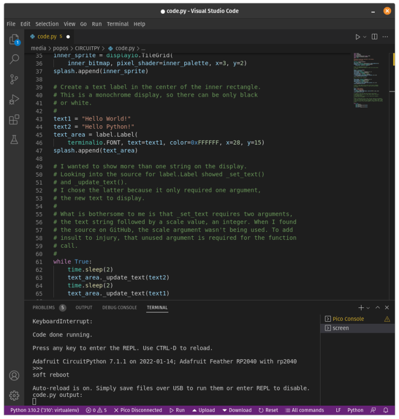
I’ve also set up my copy of Visual Studio Code as a Circuit Python development environment. I tried to install the one lone plugin that’s supposed to provide this, but it doesn’t work. In the mean time when I want to code I open the file on the devices flash drive and then open a terminal at the bottom and start screen /dev/ttyACM0 115200 which gives me the serial REPL as well as output from any print messages. Please note that /dev/ttyACM0 is the device on my computer, which is running Pop!_OS 21.10. Also note that I’ve also got VSCode set up for Pico MicroPython development which will only support Pico MicroPython development. Another post, perhaps.