my second raspberry pi 4 arrived today

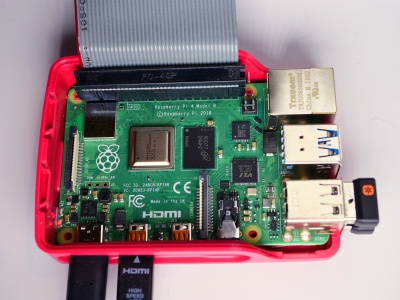
New toys arrived today. One of them was a new Raspberry Pi 4.

I ordered a second Raspberry Pi 4 with twice as much memory as the first one, for $10 more. That’s right, the 2GB version costs $45. I picked it up through Adafruit. Once it arrived I pulled out the micro SDXC card I’d been using on the 1GB version and placed it within the 2GB version. Moved over the cables and the wireless keyboard and mouse dongles, plugged in the power, and booted into the Raspbian Buster desktop. With the extra memory it appears to be a bit faster all around.

I still had to program the latest USB firmware into the chip.

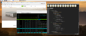
As you can see in the screenshot, the amount of swap space was automatically set clamped to 2GB. Based on my simple formula (2 times available memory), it should have been 2 times 1.8GB, or 3.6GB of space. But it’s clamped to 2GB. That’s not a problem as I discovered.

I opened up Chromium and terminal and a number of other desktop applications, and I never touched swap once. I therefore have to recommend that if you want to use the Raspberry Pi 4 as a legitimate desktop, then purchase at least the 2GB version.

I discovered that the processor temperatures are the same as the 1GB version with the heat sinks attached. That tells me the heat sinks I had aren’t useful at all. I ordered a new case from Flirc for the Raspberry Pi 4, one that has a part of the case extend down and touch the processor itself. The case is supposed to act as a big passive heat sink. They’re on sale right now for about $12/case, which is quite affordable. They should arrive next Monday. In the mean time I’ll just leave the box open and let it do its thing uncovered. Oh, I nearly forgot, the Flirc case has a slot cut in the side for the GPIO pins to be connected to external circuitry. Unfortunately for some, there are no slots for the camera cable.

working with the adafruit circuit playground express using the raspberry pi 4, part 4

Circuit Playground Express with button B pressed, switch on, and NeoPixels emitting green light

Prerequisites

A Raspberry Pi 3B+ or 4 with Raspbian Buster installed and connected to an Adafruit Circuit Playground Express via a micro USB to USB cable and with CircuitPython installed on the Circuit Playground Express (see working with the adafruit circuit playground express using the raspberry pi 4).

Circuit Python Programming Example 6

With the Circuit Playground Express still plugged in from Example 5, and with Example 5’s main.py running, we’re now going to run a Python application on the Raspberry Pi that reads the button presses from the CPE and displays them on the terminal. Here’s the code to run on the Raspberry Pi, named cpe-monitor.py:

#! /usr/bin/env python3## Circuit Playground Express example, Raspberry Pi side#import glob, serial, time, signal, sys# Use glob function to return all device file names of the form /dev/ttyACM*# I was supprised during development when /dev/ttyACM0 became /dev/ttyACM1# So we deal with the possibility of a name change in the last digit.# device = glob.glob("/dev/ttyACM*", recursive=False)[0]serUSB = serial.Serial(device, 115200, timeout=1)# Control C handler. Exit gracefully and close the USB serial device.#def sigint_handler(signum, frame):serUSB.close()print()sys.exit(0)signal.signal(signal.SIGINT, sigint_handler)# Tell the user what device name we're using, and perform a close and then# an open. Many times /dev/ttyACM* is already open when we get here.#print("Start monitoring output from Circuit Python Express on %s" % device)serUSB.close()serUSB.open()# Endless loop.#while True:usbdata = serUSB.read_until()# The USB serial device times out every second and returns if it has# not recieved any data.# If it does time out check for zero data returned.#if len(usbdata) > 0:# It's a byte array, convert to string and strip CR/LF.#print(usbdata.decode('UTF-8').rstrip())

There are far more comments than there are actual lines of code. The key lines are 12,33, 39, and 43.

  • Line 12 opens the USB connector as a serial tty device. The glob statement just above the open statement is due to the fact that it would appear that ttyACM0 isn’t cast in stone. During one run, for reasons I still don’t understand, /dev/ttyACM0 was replaced by /dev/ttyACM1.
  • Line 33 reads in the data as a byte array,.
  • Line 39 checks to see if real data has been returned. That’s because the USB serial line was opened in line 12 with a 1 second timeout. Timeouts are good because if there’s no activity you can exit and do something else. It’s a crude form of multitasking at the Python level.
  • Line 43 prints out that data after converting the byte array received in line 33 into a string and stripping off any CRs and LFs from the end of the string.

A typical run looks like this. First the A and B buttons are pressed, then the switch is turned on and the A and B buttons are pressed again.

pi@raspberrypi:~/circuit-python-express $ ./cpe-monitor.py Start monitoring output from Circuit Python Express on /dev/ttyACM0Button A pressedButton A releasedButton B pressedButton B releasedButton A pressedSwitch onButton A releasedButton B pressedSwitch onButton B released

Not too much to get excited about yet. But think about how Python code other than the print() statement might make use of these simple strings. We now have an external input device, the CPE, telling the application running on the Raspberry Pi that events are taking place. Now all we have to do is open a serial channel on the CPE to read any data that the Raspberry Pi application might want to write back as some form of confirmation of reception.

Next time…